
Micro-GT IDE MyKit.
First set available 40 € excl. Shipping costs. ad.noctis@gmail.com
The new Micro-GT product line, scheduled to be released in 2018, includes the Micro-GT My Kit, the new hardware platform that includes all the capabilities of the previous Micro-GT IDE upgrades, for which the production will stop in 2018.
The board collects all the features of the previous one, except for the stepper driver, and resolves some of the weaknesses thanks to a long testing period during which the board was used for didactic purposes.
The size of the card has dropped to about one-third despite keeping or even improving almost all the features of the previous IDE.
Micro-GT IDE MyKit 2018 Download Test program
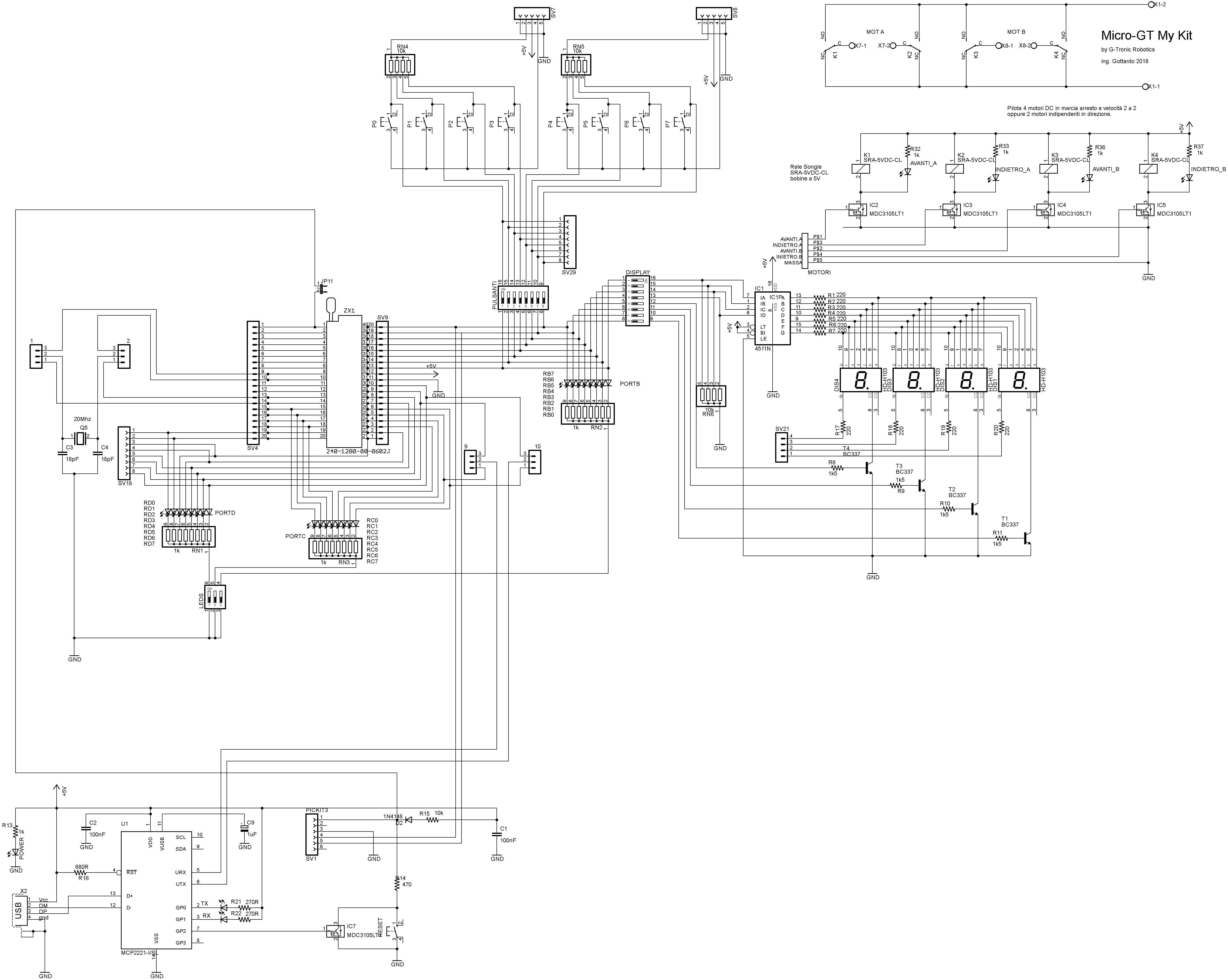
- Download schematic -> Micro-GT MyKit Scheme
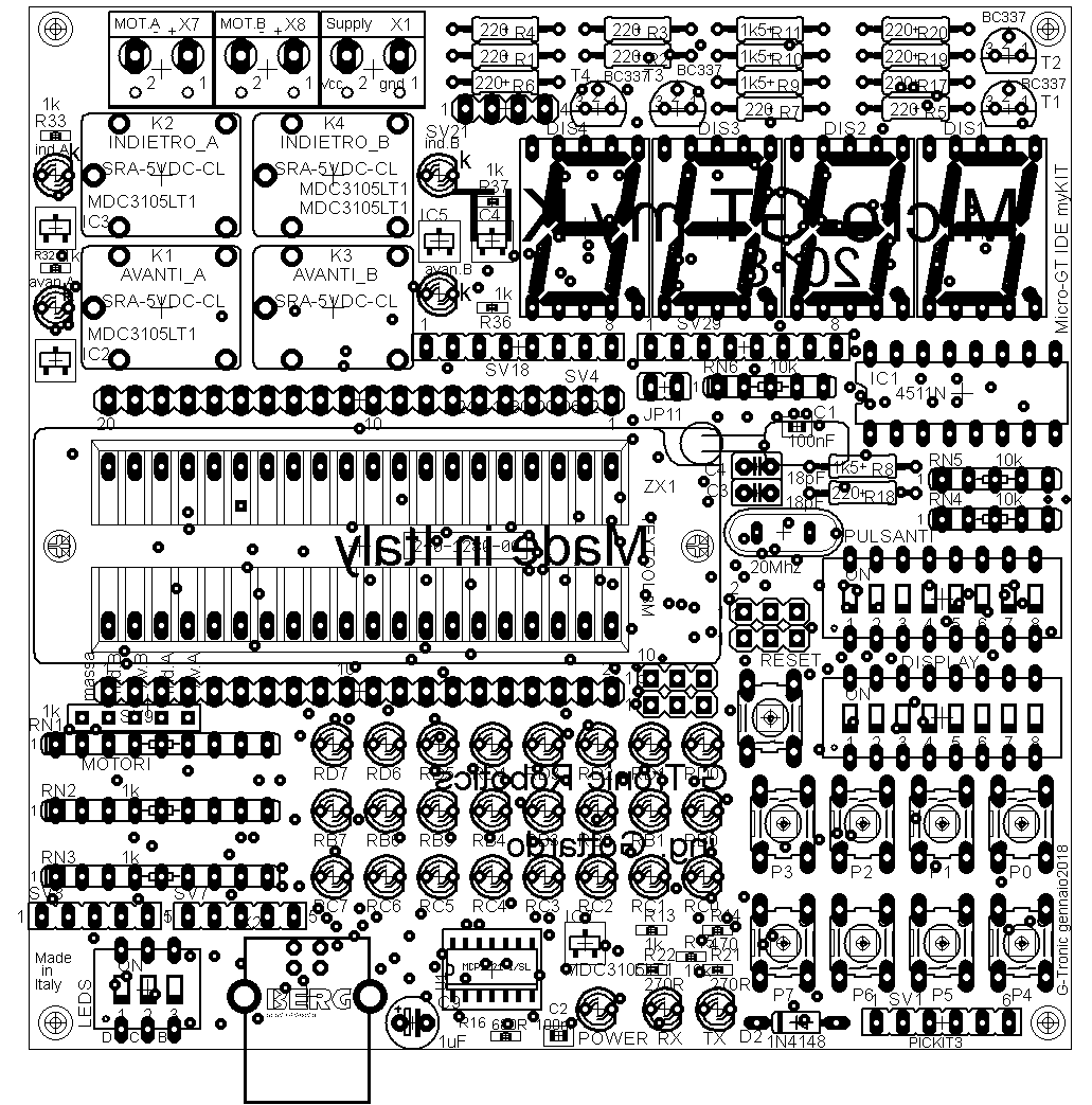
- Download Layout -> Micro-GT MyKit Layout
- Compatible PIC -> Check the compatible PIC
- Download the test program -> supercar
- Download USB communication example ->Serial_Display_MyKit2018
- USB comunication twoo motors start and stop XC8 ->Line_follower_pc_terminal
- Go to XC8 template page -> XC8 examples
- Example of I2C external peripheral RTC programming -> RTC_Project
- Complete package of XC8 exercises -> Pacchetto_progetti_PIC
- Go to Hi-Tech compilers website for download http://www.htsoft.com/
List of compatible Microcontroller device
Using the ICSP connector and PICKit 4 (or previus like PICKit3) a large set of device can be use in the ZIF socket of Micro-GT MyKit 2018. Using MCC (Microchip Code Cofigurator) you can recive a great aid in chip registers configuration. The follow is a list of tested compatible PIC. In the next Link Databook -> Demo program.
Main technical feature.
The board is designed to be assembled by the student who can also get the PCB only.
This is an important educational exercise.
The board, thanks to the ZIF socket, can accommodate a wide range of Microcontrollers: 40 pins, 28 pins, or smaller.
A wide pin header connector is placed in both sides of the ZIF socket to allow interconnection with another external interface or motor driver.
The ICSP connector, visible in the bottom right side, is available for direct programming using PICKIT3 or similar external device.
- 24 digital outputs, on LEDs, form the Italian flag.
- 8 digital inputs, adjustable pull-up or pull-down via strip header jumper.
- USB port with programming function or serial communication interface.
- Double H Bridge for the control of two medium-sized DC motors.
- 20 MHz quartz, removable for internal oscillator PIC or for 40 pin or 28 pin MCU.
- DIP switch to handle switchable bus.
- 4 digit LED display, common cathode, drived by hardware BCD decoder.
- Motors power supply separable from that of logic.
- Logic section directly powered by USB.
- PikKit2/3 connector.
- PCB dimension 10cmX10cm
Onboard DC motor interface.
The following image shows how to directly connect 1, 2, 3 or 4 DC motors.
The assembled relay is capable of driving 20A on 12V D.C. or 20A, but is suggested to stay under 10A using a 12V actuator, or 5A with a 24V actuator.
Anyway this interface is very big, bigger than what would be normally used in these kind of applications. Platfom Robots, Pan Tilt d.c., etc.
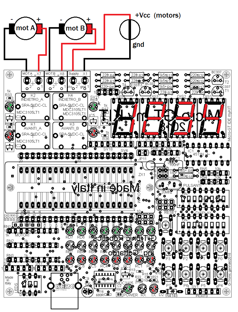
The possibility to control the speed and direction of two motors makes this board optimal in robotic applications like line followers.
The double H bridge section can be intercepted in the ground conductor with a power MOSFET in order to control the speed of the connected motors like shown in the picture.
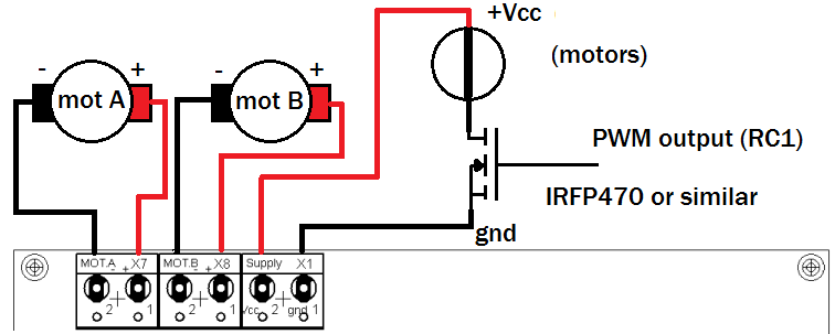
When it is not necessary to reverse the motor direction but only to control start and stop, with speed control or without, it is possible to connect 4 DC motors as shown in figure.
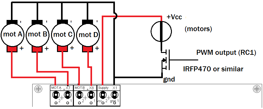
Take a look at the polarity. If it is not necessary do not use the MOSFET.
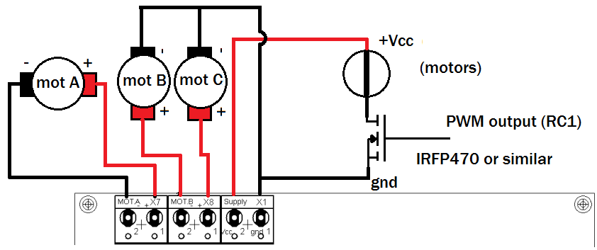
Of course it is also possible to implement a mixed solution with direction control on one motor and only start and stop control on two motors.
It is understood that the images shown above do not represent all of the controllable actuators, but those for which you have direct clamps available. It is possible to connect a very large number of external motors through external adapted interfaces.. Motor Interface
Onboard A.C. motor interface.
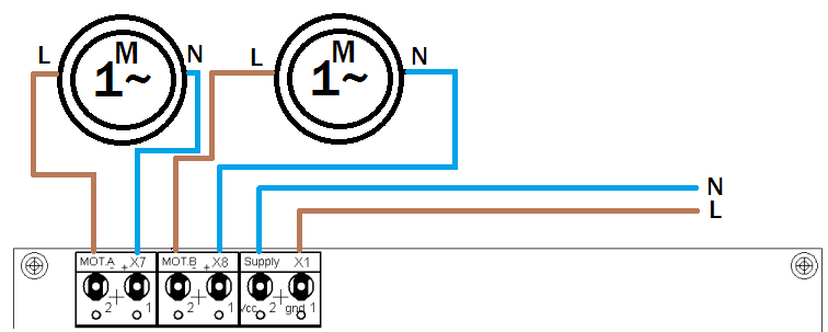
In the case of small a.c. motor, and I repeat small, it is possible to drive it using the internal relay as an A.C. motor interface.
This is made possible by the complete insulation of the relay contact section from the ground of the board.
The diagram is shown below.
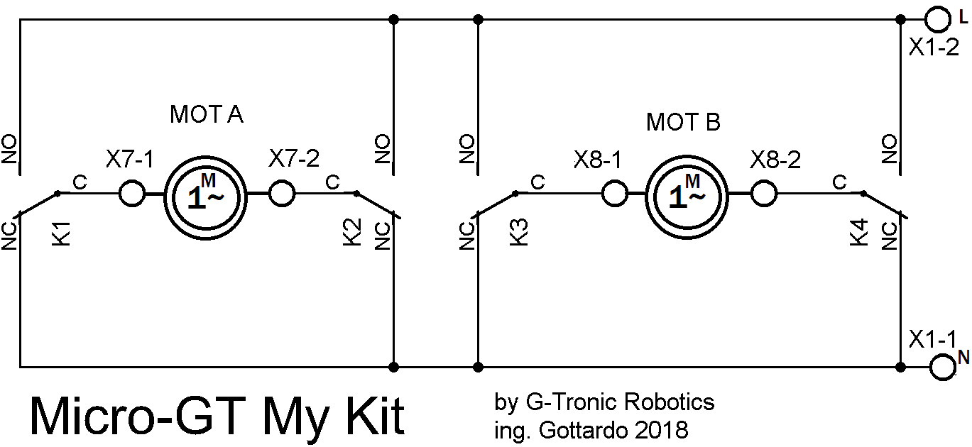
In the picture a small single-phase motor is shown. Plate data is visible.
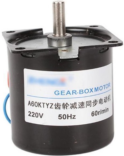
Connection diagram of a.c. single-phase motors. These are often used in indoor Pan/Tilt systems.
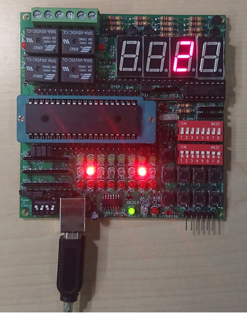
Integrated 4 digits LED display.
The Micro-GT IDE MyKit has a 4-digit LED display, common cathode, inherited from the previous version.
Hardware decoding is delegated to the CD4511 chip.
Hardware constraints have been placed for default control, the first 4 bits of the PORTB are, in ascending order, the digit generating BCD nibble to be placed in the bus.
The bus is common for all 4 digits.
The numbers are displayed by multiplexing the control transistors connected to the second 4 bit of the PORTB.
In the libraries distributed on this site you can find the source code of the “scindicifre” function that has this purpose.
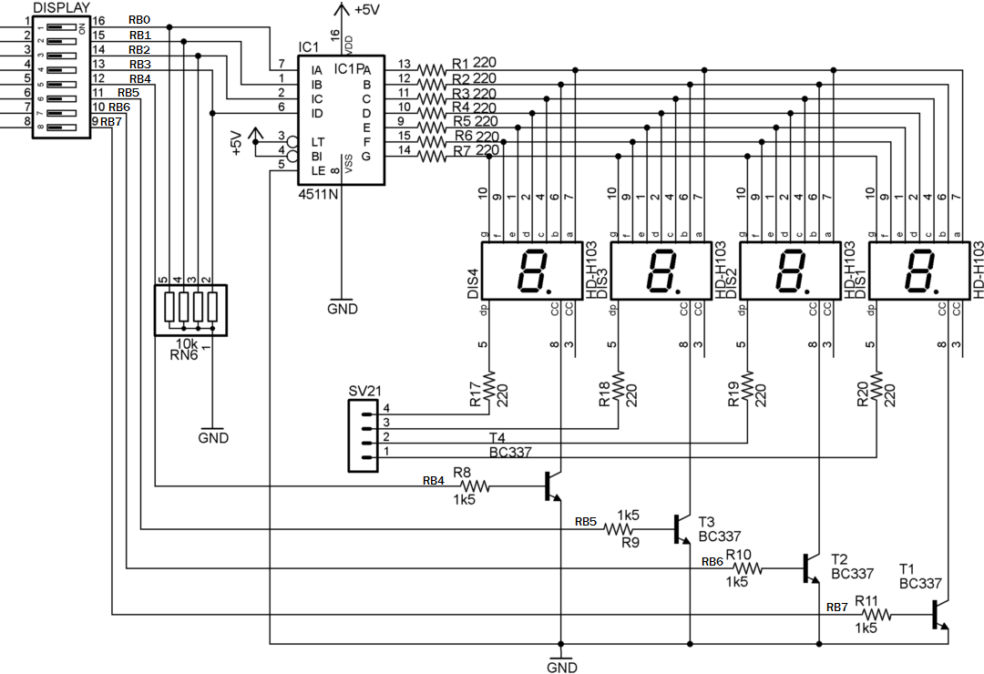
You can disconnect the display from the default lines acting on the “Display” dip, all lines or even just the cathodes control or BCD control.
The system is never floating because of the presence of pulldown resistors that force zero in the digits.
To control the decimal points a pin strip header is available, marked SV21. Connect it by a flat cable.
To control the decimal points a pin strip header marked SV21 is available. Connect it with a flat cable.
A common exercise is to display the temperature read with the LM35 sensor or the hour and minute clocks, both available with open source “C” code on this site.
Integrated 8 Digital input.
The board has a byte of buttons that is possible to switch N.C. or N.O. just moving a set of jumpers of the left side of the USB connector.
Jumpers must be inserted on SV7 and SV8, with right or left justification.
Observing the schema, in the right – justified configuration the resistors become PULL-UP and the buttons take the function normal 1–> pressed 0.
Otherwise, in the left – justified configuration the resistors become PULL-Down and the buttons assume the functionality normal 0–> pressed 1.
The board constraints impose a four by four button set.
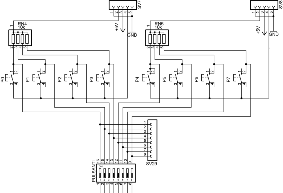
By default, the buttons are connected to the PORTB because in the baseline processor which is 16F887A, 16F887 or similar this provides hardware interrupt .
The presence of the DIP switch “PULSANTI” and the strip header SV29 allows the group of buttons to be unplugged from the bus to connect it to different points of the microcontroller. P0->P7 in mapped to RB0->RB7.
ICSP onboard connector.
There are a large number of PICs and almost all can be used in this card with appropriate fixes, for example you need to keep in mind that some PICs use 3V3 instead of 5V.
The PIN number is divided into four main families as shown in the image.
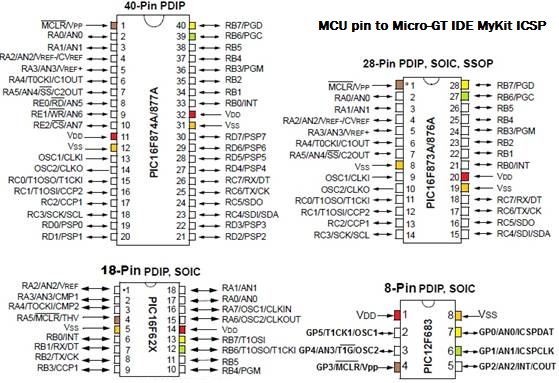
Note that the 40-pin family and the 28-pin family have the right hand side equally.
The “Program Data” and “Program Clock” signals from PICKIT are in the same location as the destructive Vpp at the pin 1, where is send about 13V to start the internal memory programming.
It follows that PIC16F877A and 16F876A (and all derivatives) are directly exchangeable in ZIF.
For all other PICs with different signal positions, it is possible to open the signal at pin 1 by removing the jumper JP11.
Basic control of two DC motors.
In this example is shown how easy it is to check in DC start and stop mode two DC motors.
Motor control is provided with 4 push-buttons, forward and backward of motorA, forward and backward of motor B.
The Laddermicro software is integrated into the GT-Pic Lab platform downloadable from this site. DOWNLOAD GT-Pic_Lab V1.1 (Stable tested version)
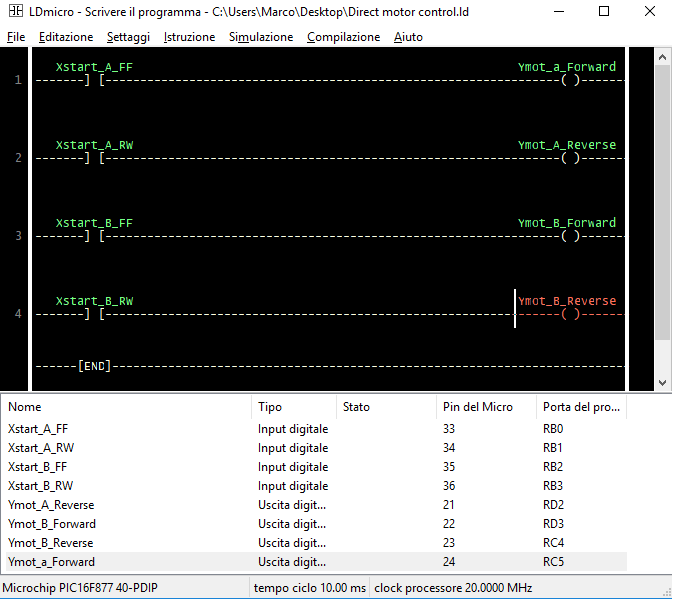
Download Ladder Micro program and compiled .hex files-> Direct motor control
In the image you see which pins are used as inputs and which as outputs.
To operate the motors, press the buttons P0, P1, P2, P3.
Observing the ladder program it is obvious that you need to set the buttons in pull-down mode then align the jumper to the left in the strip header to the left of the USB connector.
To connect the buttons to the PORTB, all DIP switches, indicated with “Pulsanti” must be set to ON, simultaneously positioning all DIP indicated with “display” switches in OFF.
Remember to short circuit, using 4 jumper, the pins number 21,22,23,24.
Micro-GT IDE MyKit 2018 – Library, Template, Tested demo program.
1) Simple example of flashing LED.
The purpose is to show the operation of T-ON timers in emulation of the DelayMs (milliseconds).
you can load this example in the PIC16F877 and 16F877A inserted in the ZIF socket of the Micro-GT MyKit, using the bootloader with which it is supplied.
Remember that if you use the PICKIT in the ICSP connector overwrite the bootloader then to resume the original operation you have to reload it. Tested bootloader is on this site.
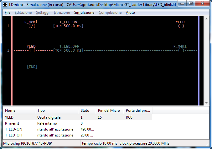
Download the .hex, .ld file -> LED_blink
Of course the same program can be implemented in standard XC8.
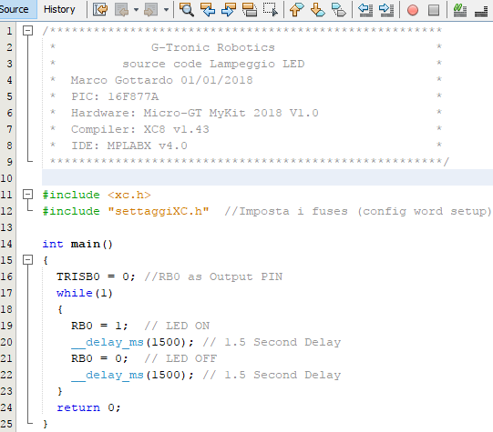
settaggiXC.h is the header where the #pragma directive setup the fuses and the used registers.
Download the full XC8 program from these link. ->XC8_lampeggio
2) Manual control of a motor
Necessary card setting.
Set RB0-> RB3 in PULL-Down. (jumper on SV7 lined up to the left).
Set RB4-> RB7 in PULL-Up. (jumper on SV8 aligned to the right).
Simple example of programming, typical of the PLC style, control of a motor with self-retain and interlocking system.
Remember that usually photocells and mechanical limit switches are usually wired NC.
Remember to insert jumper that connect the ZIF sockets 21,22,23,24 to the strip header specifically aligned to connect the motor.
Disable all switches on the DIP “Display” . Enable all the switches on the DIP “Buttons”.
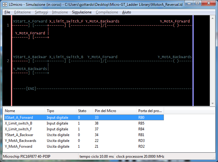
Download the .hex, .ld file ->MotorA_Reversal
3) Objects in the conveyor belt
Use the same card settings as in the previous example.
A conveyor belt brings bottles to the next machining. Every three bottles the loading system is activated in the package by activating the appropriate relay.
The photocell is connected to the RB0 input, placed in pulldown.
The output of the LED is piloted by the same end counting event.
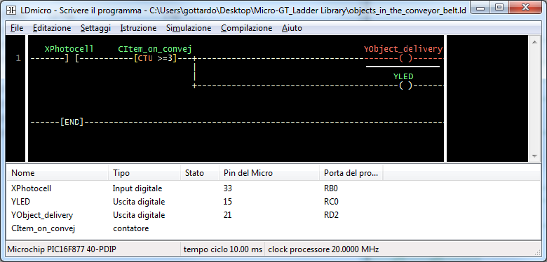
Download the .hex, .ld file ->objects_in_the_conveyor_belt
4) Simple 4 stage sequencer.
This example shows how to generate a timed sequence for drive the display generating 1,2,3,4.
Obviously it can be modified to generate any sequence, for example, to control a valve set.
The number of sequence outputs and times can be customized.
Here we limit ourselves to generating a timed sequence, with the clock shown in the first example, in the PORTB.
The example is very useful to demonstrate the operation of comparators combined with counters to generate a cyclic count.
There are 8 segments in the program, the first 5 are shown in the image.
The remaining 3 can be obtained by analogy.
The complete program can be downloaded from the link.
Set the card with the switches in DIP “Display” all ON.
Set all the DIP switches “buttons” to OFF.
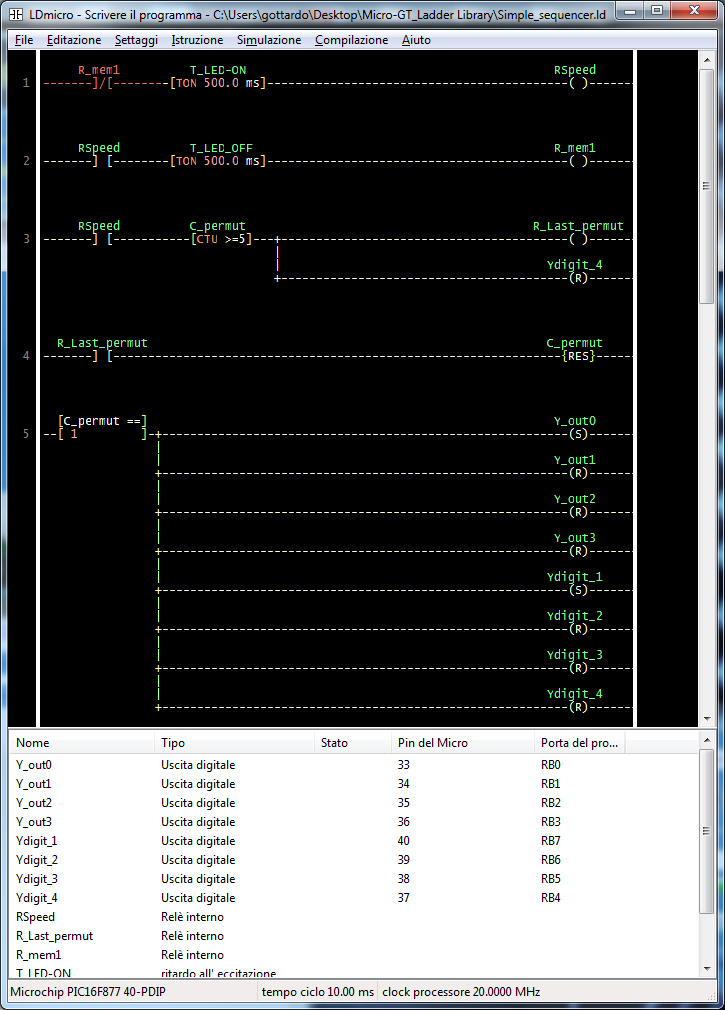
Download the .hex, .ld file ->Simple_sequencer