|
|
Scheda universale minishield 8 ingressi opto isolati |
|
|
|
Scheda universale minishield 8 ingressi opto isolati |
|
Identificazione progetto
|
progetto n.12 |
autore |
email |
note |
|
Anteprima di alcune pagine del libro di Marco Gottardo, edito in Agosto 2012. Il libro e' scritto in semplice lingua inglese, e contiene un grandissimo numero di schemi, progetti, programmi in Hitech-C, programmi in LAdderPIC, tre tesine scolastiche completamente svolte |
Marco Gottardo
|
ad.noctis@gmail.com |
Titolo del libro: Let's GO PIC!!! The book Reperibilita' Solo formato cartaceo sul sito www.lulu.com Numero pagine 450 Disponibile da fine Agosto 2012. Ordina online ti arriva per posta. |
|
Anteprima copertina, forse
cambiera' prima della pubblicazione.
|
Premessa
Dopo due anni di pubblicazione del noto corso online "Let's GO PIC!!!" sono giunto alla conclusione che il materiale poteva essere una buona base su cui impostare un libro adattto sia per la didattica, che per l'hobbistica che per il professionista. Il materiale gia' online e' solo il primo mattone di un testo che ho volutamente fermato a 450 pagine dato che e' gia' in cantiere il seguito, la cui uscita e' prevista per fine Dicembre 2012, che avra' titolo "Let's Make Robot's!!!" dai contenuti molto piu' impegnativi e che richiede come propedeuticita' tutte le nozioni contenuti in questa prima pubblicazione.
La filosofia con cui l'ho scritto e' "Learning by doing", ovvero sarete guidati passo in ogniuna delle molteplici realizzazioni. Le piattaforme sono ovviamente le Micro-GT sia mini che versatile IDE.
Riporto qui sotto l'indice degli argomenti, benche' in data odierna sia ancora incompleto lo troverete sicuramente molto ricco e suducente. La publiccazione e' ottimale per le scuole di istruzione secondaria, per la formazione professionale e le universita'. Ovviamente e' il testo di riferimento per tutti i miei corsi, sia professionali che hobbistici come quelli che tengo a Padova presso il centro culturale ZIP.
dedicated to all those who dream, invent and would create.
Marco Gottardo
table of contents and index
|
Appendix
|
Hardware and shematics
|
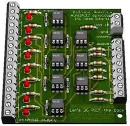
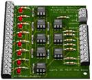
Micro-GT minishield universal 8 channel optocoupler
This minishiel is for general use, can be paired with any microprocessor or microcontroller card. The construction is simple and will operate immediately. The used components is of wide distribution. The optical separation from the outside world provides high stable operation for the microcontroller. It is essential to keep the masses always separate GNDIO (external) from GND (internal). Connect together the two areas make useless the 4N26 and there isn't electrical isolation. The main purpose of the optical isolation is to stop any pulse of high voltage induced in the signal cables.
|
|
The integrated circuit that contains an optocoupler shows 6 pin of which some are not used. There are versions for multichannels, but we decided, on this book, to use the 4N26 because it's cheap, simply to use and widespread. |
|
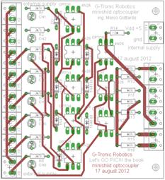
By routing with Eagle CAD we get PCBs surface of only 60mm to 80mm, very compact. The drawings, made by sch, brd, and gerber files are available free of charge from the author's website. If interested to a small series, for professional or didattic use, can be ordered by e-mail.
|
|
|
The card is designed to be mounted on normalized omega DIN guide, using the specific plastic clips. But the two holes, drilled of 3mm diametre can be aid for mount inside a chassis with other electronic devices.
|
|
On the left side of the card there are the screw terminal blocks of the inputs coming from the outside. Each input is bipolar and related to its ground disconnected from the inside one. The right side we can see a single terminal, at the top, for power supply related to the microprocessor board. The internal ground is referred by it. |
|
|
Minishiedl optocoupler top layer |
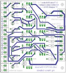
Minishiedl optocoupler bottom layer |
The remaining 8 screw terminals on the right are the outputs of the optocouplers and are already referenced to earth ground via terminal above. The applications is a lot, so you can modify some resistors values to obtain the right saturation of the internal transistor without burning the inner LED.
In some cases you can use the card to optisolare the outputs of the microcontroller to drive the Triac for circuits at 240V AC. In thease case be carefull in handly the board. For output isolation is better use a relay board.
I circuiti stampati possono essere richiesti all'autore via mail ad.noctis@gmail.com
Questo
progetto è ridistribuibile secondo i
termini di licenza![]() Creative
Commons Attribuzione-Condividi allo stesso modo 3.0 Italia
Creative
Commons Attribuzione-Condividi allo stesso modo 3.0 Italia
Note aggiuntive
Visita i siti web che ho sviluppato io, e dammi un tuo giudizio, agli indirizzi:
http://www.bb-yewilliam.it/ (il bed end brekfast di Jenny per chi fosse di passaggio a Padova)
http://www.amministrazionibugno.it/ (l'agenzia di amministrazione condominiale dell'amico Massimiliano)
/marco%20gottardo.jpg)